Making an etched kit
By Mats Björkelund, 2017-02-24
mats.bjorkelund (at) wnj.se
Etched kits can give excellent train models. By use of modern computers and professional companies it is possible for most modellers to produce their own kits. It is not simple but not that difficult either. Do not expect to be rich but it will not ruin you. This article is a personal and brief description on how it can be done.
Etching process
You do not need to know the etching process in detail but you should have a rough idea because it can influence your design.
Etching – the short version:
- A photo tool comprising two films with patterns is created from your computer file.
- A metal sheet is covered on both sides with a photo resist.
- The sheet is placed in the photo tool between the two films.
- The sheet is exposed to UV-light. Exposed areas will be hardened.
- Non-exposed areas are removed with chemicals.
- The sheet is sprayed with etching solution. Non-exposed areas will be etched away.
- The photo resist is removed using chemicals.
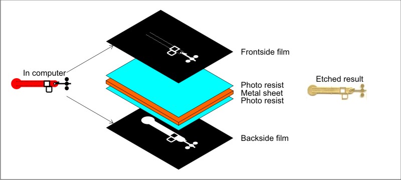
(In this case we assume negative resist. There is also a positive resist variant.)
Sheet metal and tolerances
Today it is possible to etch a variety of metals, e.g. stainless steel. My choices:
- 0.3 mm brass for normal parts. For more strength or depth: laminate two sheets.
- 0.55 mm nickel silver for more strength
- 0.2 mm nickel-silver or brass for name plates
Nickel silver is very nice to solder and many prefer it these days. But it is more expensive, it is more difficult to bend e.g. for a curved roof and it is much more prone to snap if you bend a part the wrong way.
There are effects you must respect regarding etching:
- Minimal gaps: Etching fluid has a surface tension that hinders it from reaching in too narrow gaps. Safe minimum gap is 0.2 mm. 0.15 mm grooves may work the first time but the next time you are left with a completely flat surface. Not what you had intended.
- Minimal width: Because of underetch it is not possible to etch parts under a certain width. The producers wants 1.2 * thickness of the sheet. My experience is that it is possible to go slightly below. I have made lines that are 0.2 mm on a 0.3 mm brass sheet.
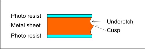
- Underetch: The etching solution will work in all directions. For thicker sheets it will etch under the resist which will make the part somewhat smaller than intended.
- Cusp: The etching solution will not etch away the sheet in the middle until just before etching is finished. This will often produce a sharp edge, cusp, in the middle of the sheet. This will make the part somewhat larger than intended.
My opinion (at least for thinner sheets): Ignore effects of underetch and cusp. Make your parts without any corrections up or down.
Select a prototype
The most important step is to select a suitable prototype. Recommendations:
- Do not select something that is already available on the market. Buy instead. It will save you a lot of time and energy, if not money.
- Select a prototype with lots of flat or single-curved surfaces. Avoid double-curved objects.
- Etching is less good for making 3D objects. Expect to buy, or create in some other way, springs, axle boxes, puffers etc. Check all parts of your selected prototype to see that you can handle such parts.
- Select prototypes you want many of. It is a lot of work with #1, much less with the following.
- You need a lot of information on the prototype. Typically you need a good drawing and a stack of photos from different angles and correct period, and preferably one example still in life.
- Do not restrict just to locomotives or wagons. There are a lot of things on and beside the railway that are suitable for etching.
- Select prototypes you love! (All modellers I have met have a bunch.) Do not select prototypes you think other people want. A kit requires a lot of work and you must be heavily motivated, otherwise there is a risk that it will never be finished.
Prototype drawings often describe what was intended by the original designer. It is not sure that it reflects what was actually built, not even once. Especially locomotives was often rebuilt and modified through their lifetime. Scale models, 1/10 or so, have the same problem as drawings. They are notoriously wrong in details.
If you must guess: Do not despair! The truth will be revealed. The first time you proudly present your work for other people. And it will not be as you guessed. Trust me, I know...
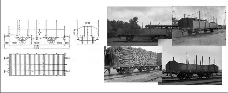
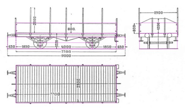
Photos are from www.samlingsportalen.se. A magnificent public collection of Swedish railway photos and documentation, administered by Swedish Railway Museum in Gävle.
The drawing is too simple but in this case we have enough information to start a project, but just.
Design
Design, or Construction, is the process where you break down the model into suitable parts and creates a plan on how to build it. Best sequence:
- Make a first design inside your head. Use sketch pad to make simple sketches. Sleep on it. Make alterations when you come up with better solutions. Sleep on it again. Make even better solutions. And so on. This is the best part of the whole project so no need to haste.
- Make a Bill of Material, BOM. Identify all parts (etched or non-etched), give them an identity number and a name (and stick to it!). Calculate how many of each needed.
- Write a first version of an assembly instruction.
- Transfer your design into a computer file. More on that later.
The first time you make an etched kit you are absolutely convinced that you do not need a BOM or an assembly instruction because your design is so clever that it is self-explanatory. It is not. Not for someone else, and not for you, in 5-10 years. If you do not believe me, buy a complex etched brass kit and throw away the instruction. Then try to build it...
Experienced designers can swap step 3 and 4 if designing something similar to a previous work. But then they probably already have an assembly instruction that can be quickly modified.
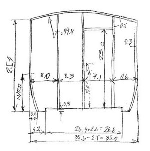 |
Make sketches as you go along. Do not make complete drawings but put in critical measurements. I often add a small formula on how I ended up with a measurement, to remember how it was calculated. |
Your job is to create an impression of a prototype, not an exact, downscaled version of it!
This is similar to a painting. If you study a painting of say Rembrandt you can swear there is a certain detail in the painting. But when you look closely there are just two or three blobs of paint. Your brain added the rest. If it looks like a sparkling diamond it probably is. The same goes for your model.
Also remember that your model is intended to be looked at from a distance. It is a good idea to decide what that distance is for you complete roster or layout. If it is 10 cm and magnifying glass is allowed you can hardly cut any corners. If it is 30 cm, and HO/OO scale, you can simplify many things:
- Skip all things less than 0.2 mm
- Simplify all things less than 1 mm
- Use small squares instead of round rivets
- Make etched handrails
- Over-size fragile things to increase chance of survival when transported
- Skip everything in the under carriage that is not seen from normal viewing angles
(I have sometimes come across kits where the designer has tried to model too much. With mega-screens and zooming it is easy to lose perspective and not understand how small parts actually are. The result is often a kit which is difficult to build, without any improvement in looks from normal distance.)
Hardware and Software
These days all computers are powerful enough for etch design. A big screen is nice but it is possible to use a laptop. To this you need a program that can handle vector graphics.
Vector graphics is where your parts are handled as small mathematical descriptions inside the program. You can easily scale or change colour of a part. (There are also graphic programs that handle pixels, like Adobe Photoshop, but they are useless for our task.)
But vector graphic programs also come in different flavours. And everyone has an opinion. Many engineers are used to drawing programs - like AutoCAD - and they often argue that x million engineers cannot be wrong. But we are not creating a drawing. You seldom fill areas with various colours in a drawing for instance. Therefore I recommend a program used for illustrations.
Possible alternatives for Windows:
Software |
Comment |
CorelDraw |
My favourite. Expensive for full version but there is an affordable Home and Student version |
Adobe Illustrator |
Expensive but used by professionals. |
InkScape |
Freeware. I have done same basic testing and it seems very capable. |
None of these are very easy to learn because they are filled with functions you will never use. So be prepared for some learning time. When you are comfortable with a program, stick to it.
From design to file
Now is the time when you should start creating your etch file, But first some things to consider.
Scale
Make your parts exactly the size you want your final parts in. Do not use prototype scale 1:1 or something else. Remember, you shall make an impression of your prototype, not a downscaled version.
It can be attempting to scale your end result to some other scale, from HO to O or so. Don´t. The basic measurements may be correct but sheet thickness will not scale. If you use 0.3 mm sheet for a HO model, it is likely you will use 0.3 mm, or perhaps 0.4 mm, in O scale. Everywhere where you have compensated for sheet thickness it will be wrong. And you will end up with a kit needing a lot of filing and filling (and swearing).
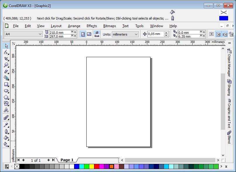
Colours
The parts you are about to create shall be colour coded. There are two different colour versions which both works well.
| Standard | Colour separations | |
| Full thickness | Black | Red |
| Half etch from front | Red | Yellow |
| Half etch from back | Blue | Magenta |
| Completely etched away | White | White |
The Standard version has been used since art work was done with ink and paper. Using photography and colour filters it was possible to separate two films. This standard is still required by many etching companies.
Colour separation is used by printing companies to create CMYK films (Cyan, Magenta, Yellow and blacK) . In our case Yellow and Magenta films are sufficient.
Which one you prefer depends on what you are used to but the end result must comply to what your etcher requires. CorelDraw has functions for easily swapping colours so it is possible to switch between them.
Layers
Illustration programs always have layers. I normally add following layers, from top to bottom:
| Layer | Use | Write protected | Included in final file |
Tabs |
Tabs that hold the parts together in a mesh |
|
Yes |
Parts |
All individual parts |
During adding tabs work |
Yes |
Measurements |
Basic measurements that define the model |
Yes, normally |
No |
Drawing |
Scaled drawing |
Yes, normally |
No |
During the process other layers can be added and layers can re-ordered to suite the task. E.g at the end the Tabs and Part layers are swapped.
Add drawing
If I have a decent drawing I think it is very conveniant to add it to the file. It makes it is easy to position e.g. windows along a wagon side without measuring at all. It should of course not be included in the final art work.
Add a drawing to your file by importing it as an image and put it on the Drawing layer. Scale the image to correct scale using measurements on the drawing. Drawings are notoriously scaled differently vertically and horizontally. The differences could be many percent. Therefore always check vertical and horizontal measurements. The drawing below was scaled 144 % horizontally but 135 % vertically to be reasonably correct.
Add basic measurements
On the Measurements layer add boxes that define the basic structure of your model. The reason for this is the problem of measuring on a drawing. If you measure the same thing twice you will often get different results.
Example: Make an outside square around the floor of a wagon. When you shall design the floor you know that this should have the same size as the outside box, minus 2 x sheet thickness on both sides. Later, when you design the sidings you know that these should have the same length as the outside box. The two parts, which are related, will get the correct size, because they are base on the added box, not measuring on a drawing twice.
Also, all programs have snap functions, i.e. if you move or stretch an object it will snap to a nearby line. This makes it extremely easy to adjust the size of a part, without reading any measurement. An object on the Part layer will snap to an object on the Measurement layer, even if this is write protected.
Use a special colour for your measurement layer, e.g. 0.2 mm lines in magenta. Magenta contrasts well to the drawing without confusing.
Add parts
Add all parts in you kit to the Parts layer. Use filled squares or circles or lines of various thicknesses. Let us make one of the parts of the wagon.
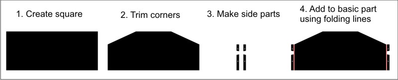
Normally give your squares/circles the exact measures you want for your final part, and with no outline.
Try putting all folding lines and half etch areas on the same side. Etching is often done by spraying from front side until it looks good. Then the back side is sprayed until etch through. If you look at your artwork most of it should be black or red, with an occational blue line or area.
Putting all parts together
After many hours you have made all individual parts. Now copy them to get the correct number of parts according to your BOM.
Place your parts in a surrounding frame. Try to use as little area as possible but do not put parts too close, minimum 0.6 mm. If you spend some extra time on this you will often find that you can squeeze in some extra useful things, without extra cost.
Add tabs
During etching your parts must hold together. If not they will drop to the bottom of the etching vessel and be lost forever. Therefore you should add tabs that hold the parts together with each other or with frames. You should always have an outer frame of at least 10 mm.
The more tabs you have on a part the less likely it will fall off during etching or handling. On the other hand, too many tabs which has to be cut and trimmed by the builder is not good either. Recommendations:
- Normally use 0.8 mm tab liness (thinner OK for thin parts)
- One or two tabs is OK on very small parts but 10-15 may be needed on large parts
- "Rather safe than sorry"
Start adding tabs with Parts layer write protected and below Tabs layer. This will make it easier to see that you have enough tabs. Using a different colour like green can also make it easier. It is not that difficult to miss that a part is lacking tabs. Trust me, I know...
When all tabs have been added, join all together and change to correct colour. Finally put Tabs layer below Parts layer.
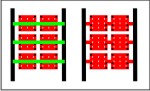
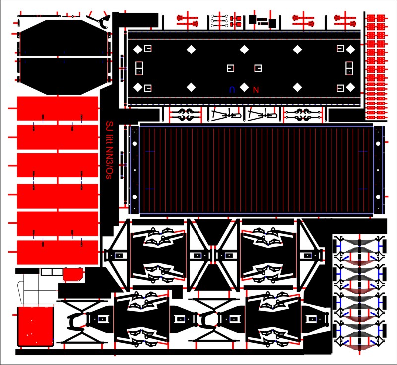
When ready you should end up with something like this.
Reduce number of parts
Putting several parts together into a bigger one will save time for the builder.
Tabs and slots
Tabs and slots will make life much easier when assembling separate parts. It also minimizes risk of putting parts wrong.
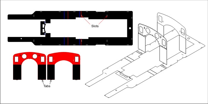
Tabs can be long or short. Long tabs can be turned on the backside which will hold the parts together temporarily. Many parts can be put together before soldering. But there will be extra work removing excessive tabs.
Short tabs just stick through the slot marginally. You have to hold the part in place until you have at least tack soldered it in but the cleaning part is more or less redundant.
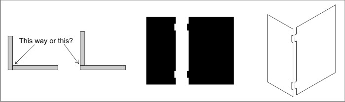
Corner problem
When two parts meet in a corner there is always a question which part goes outside the other. With a kind of tabs and slots this is easily solved and this will also hold the parts in correct position during tack soldering without any jigs.
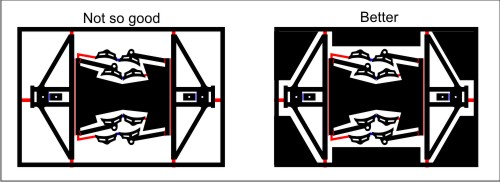
Be kind to your etcher
When etching away bare metal the etching chemicals will deteriorate. The more blank space, the faster. If you have any blank space, please fill them up with something. A thin 0.6 mm gap around parts is quite sufficient.
In windows you can put in black squares without any bindings. During etching these will of course fall off but that is OK because they will be collected in a strainer in the etching machine.
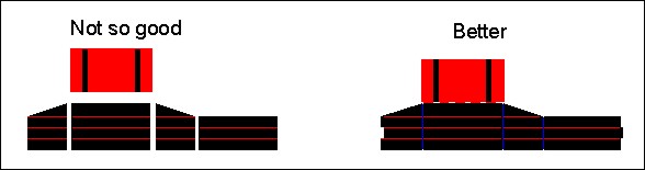
Folding
Add folding lines where you want a part to be folded easily. Make the width of the folding line the same as the thickness of your sheet. The figure below shows what measures you can expect after folding.
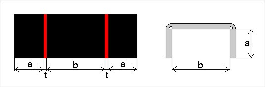
Long folding lines, e.g. for long beams, can be tricky to fold. If the folding is an inside corner, non-visable from outside, you can make the folding line split. This will make the folding line weaker and hence easier to fold.
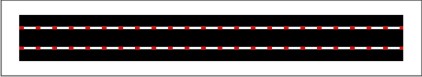
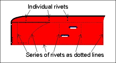
Rivets
There can be a lot of rivets on a locomotive and it can be tedious to make and position them individually. Instead you can use dotted lines. This will result in square rivets but at least in HO/OO scale nobody will notice.
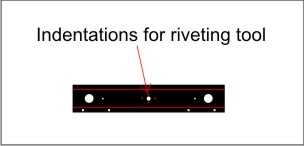
Rivet indentations
One problem with etching is that you are restricted in levels. If you have rivets on one side you cannot have folding lines on the back side. For parts with a limited number of rivets you can instead make small indentations from the back side, typically 0.2 mm in square. These can then be used as guides for a rivet making tool (or some other sharp pointed device).
You will then get rivets that stands out on the front side, while still having folding lines on the back side.
Make extra parts
A good rule is to make more parts than actually needed for your kit. Especially small parts have a tendency to fly away and never be seen again.
Learn from others (and yourself)
Stolen with pride, and improved!
This was a motto I heard while working as consultant in Bombardier, the train manufacturer. The meaning was that you should study your competitors, pick up good ideas but then improve them. You should of course not make a complete copy but including good ideas is not just legal, it is probably one of the most used methods for general improvement. IKEA has rarely come up with a unique design but they are doing quite well.
So buy kits from other manufacturers and build them. If you do not find any good ideas, perhaps you can find some bad ones that you then can avoid. In some cases I have found my own ideas included in others kits. Which makes me more flattered than irritated.
Also build your own kits. Read your assembly instruction and see if it makes sence, if the order is correct and if there is enough information. I often reorder my instructions. E.g. it is easier to solder windows on side walls while it is still flat on your table than when it has been put together into a complete body.
How thin is a line?
This question has been raised many times. How thin can I make a line without it disappearing? The answer is not simple and it depends.
TBD
Examples
Many parts on a wagon or locomotive are standard parts which are used over and over. The same goes for your etchings. To make life a little bit simpler try to make a library where you save parts which are likely to be re-used. Here are some (Swedish) parts I have collected through the years, free to use for everyone.
TBD
From file to sheet
You have created a file on your computer representing your etched kit. Now it is time to convert it into real metal.
It is possible to etch at home but you need quite a lot of equipment and chemicals. You must also find someone that can convert your file to film (“ripping”). You will not save much time or money and the result will be worse. Trust me, I have tested...
Today it is much better to send your file to a professional etcher. Depending on where in the world you are you may have different alternatives. Today, with Internet and global transports, you do not have to search locally. See special chapter for some addresses.
Visit your selected company’s website and see if they have special requirements regarding:
- Sheet sizes
- File format
- Colouring
- Costs and minimum order
- How to pay (Credit card, PayPal, bank transfer using IBAN number)
Some guide lines:
- A suitable sheet sizes could be 300 x 300 mm.
- File formats can be native if CorelDraw (.cdr) or Adobe Illustrator (.ai). Otherwise try to export to Encapsulated PostScript (.eps).
- Colouring is normally black, red, blue and white
Send a mail to your selected company with:
- File
- Request for making photo tool
- How many sheets you want
- Thickness and material of sheets
Do not send credit card number in clear text. Mail is like a post card, anyone can read. Put in encrypted file or use some other method.
Sit down and wait. In the mean time, finalize your BOM and assembly instructions.
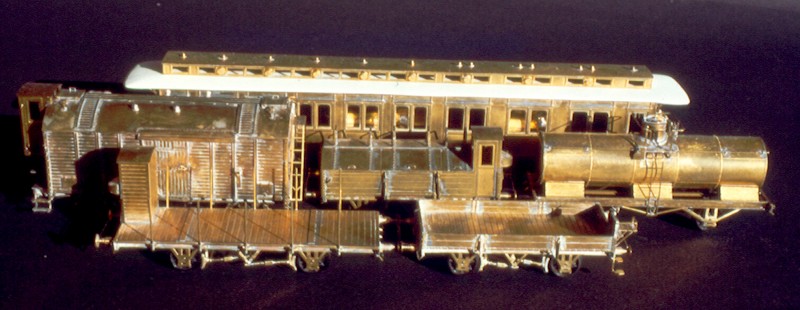
When the day comes and your first born etch sheet arrives you will be a very proud man. Even if it is of brass it glimmers as of gold!
Companies below are known for good work and are used to model train etchings.
Prices are for indication only and excluding VAT (20 %) but excluding post and package (estimate 20 GBP or more). Ask for quotation if critical.
Photo Etch Consultants Ltd
Address: Unit 19, Maybrook Road, Brownhills, Walsall, WS8 7DG, GREAT BRITAIN
Mail: info@photo-etch.co.uk
Prices:
| Item | Size | Price in GBP |
| Photo tool | 297 x 420 mm | 80 |
| Sheet | 0.3 mm brass | 15 |
| Sheet | 0.55 mm nickel silver | 25 |
Comments: Have been around for many years and are mentioned in Iain Rice classical “Etched Loco Construction”. Expect delivery times of 5-8 weeks. Some people have experienced slow mail response and their website is outdated but they do excellent work. I have paid using IBAN number.
PPD Ltd.
Address: Unit 3 Highbank Park Ind. Est., Lochgilphead, Argyll, PA31 8NN, GREAT BRITAIN
Mail: enquiries@ppdltd.com
Prices:
| Item | Size | Price in GBP |
| Photo tool | 300 x 400 mm | 41 |
| Sheet | 0.3 mm brass | 20 |
| Sheet | 0.55 mm nickel silver | 33 |
Comments: Are easy to work with and quick with response. Expect delivery times of 2-3 weeks. They have a base measurement of 300 mm width that can affect your design. Accepts PayPal but at an extra cost.
Quick Guide for CorelDraw
CorelDraw is a massive program with a lot of functions that we do not need for making etch files. The table below describes some really useful functions. (May vary depending on version.)
Combine |
Combines objects that have same properties regarding fill and outline. |
Group |
Group individual objects with different properties into a bigger one. Makes it easier to move around or rotate. |
Holes |
Can be done with Combine. |
Alignment |
To get objects aligned with each other. Hold down SHIFT and select all objects to be aligned. The last one will stay still, the rest moved. |
Copy object |
Traditional Coreldraw way: Select an object by pressing left mouse key and keep pressed. Move to other location. Before releasing left mouse key, press and release right mouse key. |
Nudge |
With the arrow keys it is possible to move a selected object in tiny steps. Set Nudge distance to 0.05 mm and Super nudge to 12x. Now you can easily move an object, or node, 0.05 or 0.6 mm. You get Super nudge movement when holding CTRL while pressing an arrow. |
Constraint |
If you press the CTRL key while doing other things you constrain the function. Very useful. |
Repeating objects |
Can be used to make many equal objects, e.g. a wooden floor. Example: |
Texts |
Use standard fonts like Arial or Helvetica for non-critical texts. If you are using special fonts, right click these and select Convert curves. The etching company cannot be expected to have all fonts installed. |
CorelDraw (the full version) contains a programming language called VBA, Visual Basic for Applications. With this it is possible to create macros that perform a set of instruction by a press of a button. Please use manual or google to find more information. Some examples useful for etching purposes can be found here (Windows only):
This file contains macros for:
- Change of colours between Black-Red-Blue and Red-Yellow-Magenta.
- Isometric macros for Front, Side and Floor
Copy file vvaMacros.gms to: C:\Users\<user>\AppData\Roaming\Corel\Graphics13\User Draw\GMS
where <user> is your user identity. The next time you start CorelDraw these macros are included and can be executed.
If working much with isometric drawing it is very convenient to have the isometric macros available as shortcut key.
Select Tools-Customization-Workspace-Commands. Select Macros from the drop box at the top.
Open the Shortcut keys tab to the right.
Select one of the Isometric macro. Click in the New Shortcut Key box. Press suitable keys and Assign.
Repeat for the other macros. I use following shortcut keys:
CTRL-ALT-F: Front macro
CTRL-ALT-S: Side macro
CTRL-ALT-D: Floor macro (D as in down)